A few degrees decide the diagnosis
A spectral-Doppler study reports a blood velocity. That number is only as good as one angle a sonographer sets by hand on every single exam: the angle between the ultrasound beam and the direction of flow. Get it a few degrees off near the steep part of the curve and the reported velocity is wrong by tens of percent, enough to push a borderline carotid stenosis into the wrong grade. It is an operator-dependent source of velocity error. Angle correction is one of the things vascular-lab accreditation reviews scrutinize.
The cost of that hand-set angle is not linear. Blood velocity comes out of the Doppler equation,
\[f_d = \frac{2 f_0 v \cos\theta}{c}\]where $\theta$ is the angle between the ultrasound beam and the direction of flow. The $\cos\theta$ sits on top of the velocity, so a small error in $\theta$ rides straight through: $v$ scales as $1/\cos\theta$, and the fractional velocity error per unit angle error is $\tan\theta$, which is why it explodes past 70 degrees. The sonographer sets that angle by hand on the scanner. A degree or two of angle error sounds negligible. Move the angle yourself and watch it stop being negligible.
θ = 60° | velocity ×2.00 | error vs 60° reference = +0%
| $\theta$ | velocity multiplier $\frac{1}{cos\ \theta}$ | error vs the 60° reading |
|---|---|---|
| 45° | 1.41× | −29% |
| 60° | 2.00× | 0% |
| 70° | 2.92× | +46% |
| 80° | 5.76× | +188% |
Near 60 degrees, each extra degree of angle moves the reported velocity by about 3%. So a model that reads the angle off the image has to be accurate to within a degree or so to matter at all. That is the bar.
Read the angle off the image instead of asking the operator to set it. Patil & Anand (EMBC 2019) showed a convolutional network can regress the Doppler angle straight from a single grayscale B-mode frame of the carotid, with no color Doppler, no segmentation, and no hand-placed landmarks, and reported under 3° mean error. I first-authored that paper. Seven years on, I rebuilt the pipeline from scratch on modern infra and tooling. I carried it end to end, past where the original two pages had to stop.
What follows is that build, stage by stage, with each stage a labeled component bolted onto a running pipeline: the data and labels, the one pooling choice that makes a frozen backbone work at all, two evaluation protocols, how far tuning and ensembling climb, and what a clinic would still need. Three questions anchor it. Does a from-scratch build hold the paper’s accuracy? Why does a frozen ImageNet backbone work at all on 84 images? And how far does the estimator go once it is tuned and calibrated? Short answers: yes, once the pooling is fixed and the head is tuned; because the vessel’s orientation is already sitting in the frozen features if you do not average it away; and down to about 2° within-population, with calibrated intervals for the clinic. The interactive write-up lives on the project site. The rest of this post walks the build that gets there.
Results at a glance. 84 carotid images, about 10 volunteers, one scanner; Apple M4 Max; Keras 3 / JAX; built test-first. Image-level holds out random augmented rows (interpolating across orientations); patient-level holds out whole volunteers (cross-subject).
| The core model | A frozen DenseNet201 plus a small head lands at 5.84% MAPE (3.77° MAE, $R^2$ 0.982) once the pooling is fixed, with no fine-tuning - close to the EMBC-2019 single model (4.03% / 2.87°), which the tuned model below actually matches. |
| The pooling insight | Global average pooling is approximately rotation-invariant, the wrong bias for an orientation target. An orientation-preserving grid pooling head lifts the same frozen backbone from about 14% to 5.84% MAPE with no fine-tuning (single-split figures; the matched cross-validated pair is 10.85% GAP vs 4.58% grid image-level, in the figure below). |
| Best estimator | An Optuna-tuned 5-model stacked ensemble reaches 2.79% MAPE / 1.96° image-level (whole volunteers in play), and 8.53% / 5.93° patient-level (whole volunteers held out). |
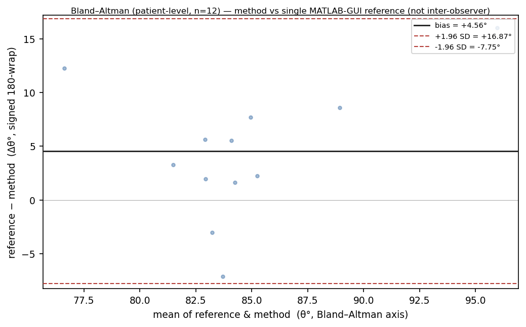
| Clinical-grade | Split-conformal 90% bands of ±20.5° at 95.2% coverage; on Bland-Altman the model reads about 4.3° below the single reference reading; rotation test-time augmentation cuts base-image error 7.8° → 4.7°. |
Labels from rotation
The pipeline starts before the model. The cohort has no clinical angle annotation, so $\theta$ was hand-drawn once per image in a MATLAB GUI. That single reading per base image is the only ground truth. To turn 84 readings into a regression corpus, each base image is rotated through $[-60°, +60°]$ in 5-degree steps, 25 oriented views apiece, for $84 \times 25 = 2{,}100$ labelled views. The label of a rotated view is exact: the new angle is the base angle plus the rotation. Because the increment is exact, the network learns to read relative image orientation. The rotation sweep does double duty as augmentation and label source.
Those 2,100 views are not 2,100 independent observations. They are 25 geometrically coupled copies of 84 base images drawn from about 10 volunteers, a three-level hierarchy of volunteer, base image, and rotated view. That coupling matters later. It is why there are two ways to score the model.
The pooling head
The whole project rests on one head choice, so look at it fail first. My first frozen-feature runs landed near 14% MAPE (mean absolute percentage error) on a single augmented split. The obvious read is that frozen features simply cannot reach fine-tuned accuracy, and that read is wrong.
The culprit was the pooling. Global average pooling collapses an $(H, W, C)$ feature map to a length-$C$ vector by averaging each channel over every spatial position; average out where a channel fired and you keep only how much it fired, which is roughly invariant to rotating the image. For classification you want that invariance. Here the target is the vessel’s orientation, encoded in the spatial layout of the activations, so GAP averages away exactly the signal the model has to read. It was throwing out the answer.
Grid pooling keeps it. Instead of collapsing to one vector, average-pool the final feature map onto a coarse $G \times G$ grid, then flatten; now a top-left cell is no longer interchangeable with a bottom-right one, so the flattened vector carries coarse spatial location and the head can read orientation off it. On a single augmented split, frozen DenseNet201 with grid pooling reaches 5.84% MAPE, 3.77° MAE, $R^2$ 0.982, with no fine-tuning at all - close to the EMBC-2019 best single model (about 2.87° / 4.03%), though it does not match that number until the head is tuned.1 The work is in not pooling it away. A frozen ImageNet backbone already sees the vessel orientation.
Two ways to score
That core model now has a number on it. Which number depends on how you split the corpus. The hierarchy from the label step forces the question.
Image-level: held-out rows scatter across every volunteer, interpolating across orientations. Tuned ensemble: 2.79% MAPE / 1.96°.
Image-level sampling is the paper’s protocol: split at random over the 2,100 augmented rows, which measures how well the estimator interpolates across the full population of orientations. Patient-level sampling holds out whole volunteers using GroupKFold over patient id. The test anatomy is then unseen at any rotation. It is the stricter, cross-subject lens, and the one a clinic cares about.
That gap is the measurement. The tuned ensemble scores 2.79% image-level and 8.53% patient-level, about a 3-fold spread that quantifies how much of the within-population accuracy is anatomy-specific rather than general. One caveat stays attached. The patient groups are 12 time-clustered proxies recovered by clustering acquisition timestamps, not verified subject identities.2
The climb: tuning, then ensembling
With the core model fixed and both protocols in place, I went looking for accuracy. First, a reasonable thing to try and a quick negative result: newer encoders. They are not better here. A frozen-feature bake-off across the modern zoo, run at a common grid so the encoders compare like for like, leaves DenseNet201 (14.13% patient MAPE) below ConvNeXt-Base (15.65%), ConvNeXt-Tiny (16.07%), and the EfficientNet / V2 family (roughly 17-21%). That 14.13% is the common-grid bake-off entry; DenseNet201’s own tuned 3×3 grid reads 12.59% patient-level in the pooling and climb figures, which is why its two patient numbers differ. With only 84 base images, the ranking is empirical: these frozen feature spaces happen to encode the orientation cue better, and the newer encoders do not buy anything here.
So the gains had to come from the head, not the encoder. An Optuna TPE search over the head and optimizer, run on cached frozen features, moves single-model DenseNet201 from 4.58 to 4.03% image-level and 12.59 to 10.80% patient-level in the search’s own validation (10.14% when re-scored on pooled out-of-fold predictions, the protocol the figure below uses): a real but small gain, and 4.03% is where the from-scratch build finally matches the paper. These tuned single-model figures are in-sample to the search, so read them as optimistic. Each trial is a shallow head fit. One feature extraction per backbone serves both protocols, and no GPU is needed.
Stacking the five tuned backbones (DenseNet201, VGG19, ResNet50, Xception, InceptionV3) is where the accuracy actually moves. A Ridge meta-learner on pooled out-of-fold predictions reaches 2.79% / 1.96° image-level and 8.53% / 5.93° patient-level. That is the first configuration below 10% MAPE cross-patient. Read against its like-for-like predecessor, the single tuned DenseNet201 on pooled OOF (7.80° / 10.14% patient-level), the genuine ensembling gain is about 1.9°. The plain mean of the same five lands at 9.89% patient-level. Before tuning, that mean was a useless 21.9%. Tuning calibrated the members just enough for averaging to help at all.
A number needs a band
An accuracy number is not yet an instrument. A clinic acts on a number with a band. Three post-hoc checks on the held-out patient-level predictions say how far this is from usable.
Split-conformal calibration, with a patient-disjoint calibration set, gives a 90% band of ±20.5° at 95.2% empirical coverage. That is wide, roughly 41 degrees of total width. It is the price of distribution-free validity on a cohort this size. A conformal interval covers the truth at a stated rate without assuming a noise model, and here coverage sits at or above nominal. So the band is not optimistic. That 95.2% is one seed-42 patient-disjoint split. The marginal-versus-conditional-coverage caveats live on the project site.
Agreement comes from a Bland-Altman plot against the single MATLAB-GUI reference reading: the model reads roughly 4.3 degrees lower, a per-sample bias magnitude of about 4.3°. With exactly one human reading per image, this is method-versus-reference, not inter-observer agreement, and I will not invent a second reader to make the plot look more clinical.
Rotation test-time augmentation buys accuracy without retraining. The 25 views of a frame get de-rotated back to base and reduced circularly (180-periodic, seam-safe so a straddle of the 0/180 wrap does not corrupt the average), which cuts base-image MAE from 7.80° to 4.72° with the circular median, about a 40% cut. It costs 25 forward passes per image. That 7.80° base-image footing sits on a different split from the 5.93° patient headline, so the two do not line up directly. The project site works it through.
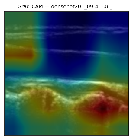
Grad-CAM, finally, lands on the carotid wall, the boundary that fixes the flow axis. The network is reading anatomy, not label burn-in. The pipeline is now whole: rotation-built labels, a frozen backbone read through grid pooling, scored two ways, tuned and stacked, then wrapped in a calibrated band and an attribution check.
Where it reaches next, and where the ceiling is
So where does the method go from here, and what stops it? Two answers, and they point in opposite directions.
The next reach is concrete. Modern self-supervised encoders, DINOv2 or a medical-ultrasound foundation model, are the obvious successors to a frozen ImageNet backbone, but they need a CUDA box and a reworked dependency stack. A hand-crafted structure-tensor baseline (MAE 3.16°) with a learned-plus-classical circular fusion (2.72°) suggests the learned and geometric cues capture partly complementary signal, which is a thread worth pulling, though both figures are in-sample on a narrow base-angle band.
The ceiling I actually hit is hardware, not tuning. End-to-end fine-tuning of the strong backbones OOMs the Apple GPU even at batch 16. A from-scratch CNN fails outright (MAPE around 101%, negative $R^2$). For 84 images, read those two failures as positive evidence that frozen transfer is the right tool here. The small-data regime was telling me what it wanted.
Everything traces back to results/: the library is typed and test-driven, and every figure here regenerates from script at seed 42, nothing hand-typed. What began as one hand-drawn angle per image is now an estimator that reads it back to within a couple of degrees, wrapped in a calibrated band you could hand a clinic.